


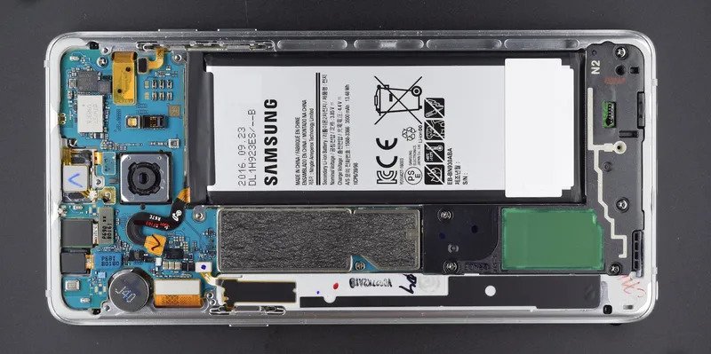
When Sam and I decided to tear down a Samsung Galaxy Note 7 to see if we could understand why some of them had caught fire, we didn’t just rip it apart and take some photos. We engaged in a real failure analysis (FA) process. Properly executed FA is an important skill for any hardware engineer: if you can extract the right evidence from the failing unit, you can find the root cause and correct the issue.
We bought our unit from someone on Craigslist—and while it had not caught on fire (yet), we started with a theory that there was a fundamental design flaw that motivated Samsung to not only cancel the product, but also (since we published our teardown) to release a software update to brick those that remained in the field. By that logic, even our humble unit should have evidence we could find.
First, we ignored all of the theories we had read and focused on making a list of the key things that could go wrong from a design or implementation perspective that would result in a fire. Ranging from part quality to design issues, these became our hypotheses.
We then proceeded to carefully tear down the unit layer-by-layer to find evidence that either supported or refuted each hypothesis. We used an Instrumental inspection station to document each step of the teardown, and were able to eliminate six hypotheses through visual inspection alone and hone in on what we believe is the true root cause: a design flaw that did not leave enough thickness for the battery. Had our system been in use on a Samsung Note 7 assembly line, images would have been collected while the unit was being assembled, and an engineer could retroactively inspect both good and bad units to get multiple proof points to support a hypothesis. Those engineers would even be able to inspect the units that caught on fire out in the field, potentially seeing evidence that was destroyed by the fire itself.
Hypotheses
Potential Root Cause #7: Physical damage to the battery pouch, folds, or insulation tapes
The image shows the battery pouch, folds, and insulation tapes are all in good condition. This is unlikely to be the root cause.

Potential Root Cause #6: Damage to the Power Control Module which could cause a short circuit
The image shows no sign of damage to the insulation tapes that cover the Power Control Module. Underneath, there is no obvious damage to the board itself—everything is pristine.

Potential Root Cause #5: Damaged or missing thermistor on the Power Control Module (PCM)
A thermistor is a component that measures the temperature of the surrounding area. Charging a battery at high temperatures (above 65 C) could result in a fire, so the PCM circuitry uses the thermistor to shut off charging if the battery starts to get hot. A damaged thermistor could cause a fire, but we see no signs of component damage or vulnerability.

Potential Root Cause #4: Damage on the battery flexible circuit board causes a short circuit
While there is a superficial scratch on our battery rigid-flex (a circuit board that has both flexible and rigid sections), it otherwise appears to be in excellent condition. The flex itself lives between two smooth parts in the system, so even if it got squeezed, it would be fine.

Potential Root Cause #3. Something nearby punctures or protrudes into the battery
After reviewing the images, the battery is enclosed in a machined aluminum pocket on four sides—lateral poking seems very unlikely. In the thickness direction, the battery is sandwiched between two smooth parts: an aluminum wall between the battery and the display and the inductive charging flex. This is all evidence that care was taken in the design to explicitly prevent this particular issue.


Potential Root Cause #2: Overheating of the battery due to proximity of wireless charging coil
If this were the root cause, there would be an underlying thermal design issue with the system. Optically, we are able to see that the charging coil appears to be properly assembled, fitting precisely in the negative space created by the locating features around the flex. So while our FA was able to eliminate workmanship or process related issues, there might be a thermal design issue that would involve further investigation and testing.

What that leaves…
At this point, we’ve inspected and quickly eliminated six potential root causes using images we captured with our instrumental system. In the real world, that could be six investigations or experiments saved from the comfort of an engineer’s desk. And for our teardown, that left a couple last hypotheses to investigate by hand.
Potential Root Cause #1: Battery does not have room to swell, putting pressure on the battery
Batteries swell over time with normal use, and therefore the mechanical design needs extra “ceiling space” to accommodate a thicker, swollen battery. As product design engineers, we call this thickness direction “Z” (where “X” and “Y” are oriented along the width and length of the device accordingly). A conservative rule of thumb for battery swell is 10% of the battery’s thickness, though many battery vendors pride themselves on designs that swell only 7% or 8%.
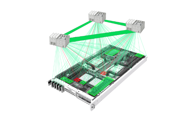
In order to understand how much space was available in Z, we did a “Z-stack exercise” to identify and measure all of the components that contribute to this critical stackup in the product. Take a look at the diagram—which is also explained in the bullet points below.

The product has 5.60mm of Z space available between the back-plate and the machined aluminum ceiling. (5.50mm from the enclosure pocket itself, plus 0.10mm of back-plate adhesive thickness)
Subtracting out 0.45mm for the charging coil and 0.1mm for the battery adhesive, which also live in this thickness, leaves 5.05mm for the battery itself—when maximally swollen.
That means the actual battery we measure should be 4.59mm (or slightly larger, as our battery is not new), which when combined with 10% of its thickness (0.46) should not exceed the 5.05mm space available.
What we actually found is that the battery is 5.05mm thick, essentially the same size as the available space. This is what mechanical engineers call “line-to-line”. In the short term, the effect is that the battery is in the “compression stack” of the product: when any kind of pressure is applied (such as if it’s in your back pocket and you sit on the couch), that pressure is actually compressing the battery too. Putting pressure on lithium polymer batteries increases the risk of fire. In the long term, the battery will swell by up to 0.5mm into space that does not exist—which will increase the pressure and potentially push the product apart. This swelling happens at the atomic level as Lithium atoms move around, and will “literally lift a house” as a battery engineer friend put it; it definitely cannot be contained by a couple of parts held together with adhesive. This is a major design issue with the product as a whole that, short of a complete overhaul of the entire product, could only be fixed by putting in a smaller battery with lower capacity.
Potential Root Cause #0: Battery has an internal design or manufacturing issue
Investigating this hypothesis would require opening the battery itself, and so we did not do this for our own safety. For this one, we leaned on Samsung’s own report that there were manufacturing issues that caused some battery layers to be too thin. Specifically, thin insulation layers would make the battery even more susceptible to damage from pressure, either from battery swelling or external compression. The combination of a line-to-line design that allows external pressure on the battery and this manufacturing defect is our leading theory for what went wrong with the Note 7.
Failure analysis is a messy process
I know we make FA look easy, but as with many things in hardware, the reality is that it is messy. Just getting access to the “bodies” of failed units is not always trivial—sometimes those units have already been shipped to customers, or are in a factory thousands of miles away from the engineer who needs to do the analysis. Often, even when you are careful, opening a unit can damage the evidence, or even change it to make it misleading. As a result, CT scanners, X-ray machines, and cross-sectioning equipment have become standard in the failure analysis process, but still don’t really solve these problems.
This was one of the motivating pain points for the Instrumental system. Many of our customers just want to “see everything inside” without actually opening their units. Instrumental enables them to collect images and other data as a unit is assembled, creating a virtual record that can be reviewed before a unit is torn down for FA. Even during teardown, some customers capture images in our system so they can use our software tools to easily inspect, compare, and measure the “before” and “after” views. Sometimes, this FA can even be done remotely.
I am often asked what percentage of product issues the Instrumental system is able to assist in solving. The answer is most, if not all. When you first identify a failure, there are often many potential root causes that have to be explored—like those we identified for the Galaxy Note 7. Many times, our customers are able to definitively see the root cause in one of the photos or other data they are reviewing. Other times, even if the root cause is not visible, it’s possible to eliminate potential paths of inquiry that normally would have to be investigated. Such as for the theory that the charging coil was getting too hot, we were able to eliminate workmanship issues because we could see that the coil was properly assembled. This enables the limited engineering and factory resources on a given hardware program to focus on the theories that are most likely to lead to root cause—saving lots of time and effort in the process.
See how Instrumental can streamline your issue discovery and failure analysis process by requesting a demo.
Author
Related Topics