


While it can be frustrating to deal with at the time, resolving failures and getting to a defect free launch is one of the most satisfying parts of product development. Understanding how to detect failures, where to look for them, and common failure analysis methods can add structure to your workflows can reduce the number of mistakes in your program improving your product’s chance of launching on time and on budget.
Because it is so hard to know where to start, Instrumental’s team of product design engineers has written this 3-part series to help you. In Part 1 below, we will discuss tools you can use to identify common sources of problems and ways you can reduce issues in the first place. Part 2 will dive deep into common failure analysis processes and techniques and Part 3 will introduce you to some key questions to ask during failure analysis.
Nobody wants to deal with failures, but it’s best to be prepared when they happen. We continue to be advocates of prevention as the best way to reduce problems, so it helps to be organized and vigilant from the beginning in recording as much information as possible about the design. Document how your product moves through the supply chain and the assembly line and how failures were induced and identified. The more good sources of information you have, the better equipped your team will be to tackle failures that will inevitably occur.
Key Takeaways
- Create documentation and test criteria to detect issues in your development builds especially those that occur at critical junctions
- Critical junctions in your development occur at any process step that changes the form or function of the product or could expose the device to damage.
- Many silly mistakes can be mitigated through improved processes and checklists.
- Make sure to refine your development processes based on past experiences.
- For any other issues that come up, see the next articles on this topic.
Sources of Product Failures in Development
Everybody knows what failures are – or do they? There are obvious issues where something doesn’t fit right or breaks in a test, but in reality failures occur in a lot of places throughout the development process. Because there is just so much to be done and so many parties involved, each step along the way is a potential source of error which can cause unforeseen issues at the prototype line or in consumer use.
Since you cannot perform any kind of analysis on issues that go undetected, Failure Analysis starts by understanding where these issues come from. This means knowing what failures are and how to detect them. Then you can triangulate where in the development cycle different types of problems occur and put processes in place to mitigate the most egregious errors. If you don’t spend time adhering to these processes, something could be missed early on in the design, propagate through development, and end up in your finished product.
Finding Failures Across The Line
The best way to find failures is to implement inspection processes and tests at critical junctions in your product development. Critical junctions occur any time a process is performed that changes a product’s form or function or exposes the product to extreme conditions. Examples include handoffs between companies, such as tool release or when parts are shipped from the supplier to the contract manufacturer. They also occur on a smaller scale within the factory when parts are added to assemblies and assemblies are moved from one station on the line to the next.
Finding Failures in Mechanical Drawings
Starting with design, if something isn’t a perfect recreation of your CAD files, you need to be able to determine what level of divergence is acceptable and set pass/fail limits. Dimensional tolerances on the drawings should match the limits in your design based on your tolerance analyses, but they must also accommodate the process capabilities of your suppliers. Dimensions that are too loose may cause fit and finish issues, but too tight and you may have a high yield fallout.
Critical to function features should be measured across a statistically significant sample set to verify the parts will fall within the tolerance range. These important dimensions should be measured by your supplier at their Outgoing Quality Check (OQC) and your contract manufacturer at their Incoming Quality Check (IQC). Ideally, measurements would be performed using the same setup, equipment, and technique so they would correlate well. But don’t assume that every part will be measured fully because checking all critical dimensions on every part would be rather time-consuming.
Finding Failures in Assembly Line Processes and Tests
During the FATP process, your operators will be trained to follow the Standard Operating Procedure (SOP). The more time your team spends in reviewing every detail of the procedure before the build, the better you can catch potential errors and determine how to deal with any failed assemblies. Everything from the order in which you screw components together to the position of an excess cable slack should be defined so that you can be confident that each device will be built consistently.
Similarly to dimensional tolerances, functional tests for input and output components also require limits. These limits should be set between the minimum level for acceptable functionality and maximum theoretical performance. If you are unsure what those limits should be, you can set them at each test station using gauge repeatability and reproducibility (GR&R) testing prior to the main build start. Ideally, you will get a narrow band of performance variation for key components that also fits within the theoretical limits. As you progress through the build, keep an eye out for devices that drift out of the initial ranges and if necessary make adjustments.
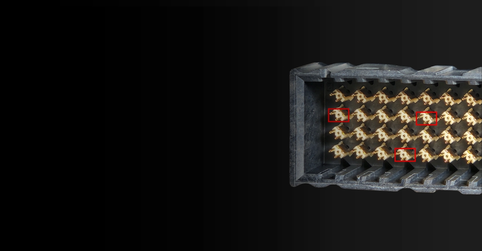
With all of the handling in the chaotic process at prototype builds, make sure to include visual inspections throughout the process and especially with any blind assembly processes. This is incredibly useful before and after blind assembly steps especially when dealing with fragile cosmetic components with special finishes like paint or anodization. Small undocumented processes on the line like how the product moves between stations or the way a particular test station clamps onto a product can damage unprotected components.
With visual inspections, make sure to have good lighting conditions for viewing and look from several different angles. Early build inspections might also include a shake test for unusual rattles from extra parts or loose screws.
Stopping the Line
During prototype builds, it is important to stop the line if an issue has been raised so that subsequent devices don’t get built with that particular issue. The purpose of the build phases are to catch issues and fix them before entering into mass production and the earlier the better. So use this key lever in failure identification and allow your team to pause, take stock of the situation, and make a plan for how to fix it.
Where Problems Occur
Using the detection methods above you can identify sources of error early. Even better would be to prevent them from happening.
At Instrumental, we like to break sources of failure into 5 categories. Each of these categories represents a significant phase within development. Because different stages of development introduce different kinds of errors, you can incorporate the detection methods above into development processes to prevent issues from propagating too far.
1. Design and Architecture Failure Analysis
Design and Architecture failures occur when something was missed when creating the fundamental product architecture and translating that into the 3D CAD models. Before the design is locked is the best time to find and eliminate failures because you have the most flexibility to make changes. However, it is challenging because you don’t yet have a good understanding of how the product will perform in real life. You may also have a tight schedule and many stakeholders to satisfy. Just remember that once you commit to a large spend for a build or tooling the impact of each mistake grows and it becomes harder to fix.
Sometimes, design failures are silly mistakes like a missed interference or misplaced feature that failed to account for how the product would be assembled. Other times, you may be pushing the envelope of process capabilities to meet industrial design goals only to find out later that it wouldn’t work. The more complex a design is, the more likely small issues will compound into large problems.
One particularly painful experience one of our engineers had was with the design of a really simple flexible printed circuit (FPC or flex). To put it simply, the FPC was just a flat wire, with connectors on both ends and some traces in the middle, making the design easy to rush through. But the engineering team missed that one of the signal vias was exposed to the grounded mechanical stiffener on the back. This meant the very signal the flex was designed to transmit was tied directly to ground, meaning the entire flex was useless.
To solve this issue, the team had to re-spin the design and get new flexes made, which took 3 weeks, all because they did not spend 30 minutes to thoroughly check the design. For complex things like this, the engineering team developed a checklist (essentially a list of all the things that have gone wrong before) to check on every new design. Keeping that list up to date with each new issue will save you from repeating the same mistakes over and over.
To combat these challenges in the design phase, be sure to budget the appropriate amount of time for design reviews. This time should correspond with the complexity of the design and risks the team is taking with each program. In the design reviews, the team should describe the main architecture, major components, critical stackups and tolerance analyses, and potential risks with the design and how they were or will be addressed.
Using tolerance analyses and experience with tooling and manufacturing processes, you can set the initial limits in your dimensioned drawings. But you will still need to go through the Design For Manufacturing (DFM) review with your vendors to make sure their tooling capabilities can meet your designed tolerances. If they can’t, you may need to either rework your analyses and update the CAD to reflect what is possible or work with your process teams and vendors to look for any new ways to guarantee tighter tolerances. It is important to use your experience and judgement in assessing the risk of either option which might include the time and cost associated with additional investigations and retooling.
Cross-functional teams should review and approve how critical components like antennas, displays, and speakers connect to the main board and are retained in the housings. Use these reviews to probe for deal breakers for each team. This can help bound your choices if you need to make design changes in the future. For example, if a metal rib is under consideration to stiffen the structure, make sure to discuss this with the antenna team if it might change the expected performance.
The operations teams responsible for designing for assembly (DFA) processes and fixtures should also understand the design intent and recommended method of assembly. This allows them to design the line around the way the device fits together and make fixtures and test methods to minimize cosmetic damage. Quick, simple prototypes that are 3D printed or CNC machined can help the team visualize how the parts fit together and brings an element of scale to discussions about feature sizes. They are also great sanity checks for sizing test fixture nests.
Be wary of last minute changes to critical features and encourage the team to hold another design review if anything substantial needs to change. Mistakes often crop up when your teams are rushing to meet a deadline. Scope or design changes at the last minute often go unchecked as your engineers try to slip in the change just before tool release. Even if you release your parts for tooling 1-2 weeks later than you would like, you will inevitably save a lot more time and money by finding issues before they are built into tooling. Also if you find any issues along the way, record them so you can collect them into a checklist for the future use. Learn how P2i engineers tripled their FA efficiency with Instrumental.
2. Component and Supplier Failure Analysis
For any custom part, your vendors have their own development process to design the tooling, cut the steel, and ultimately create stable, quality components. Some manufacturing processes are well established and easily modeled, but if you are pushing the limits with your design or the timeline, be prepared for some delays while their team dials in the processing parameters.
Be careful of using first shot parts for anything other than fixture validation as they can have a wide array of quality problems. Anything from missing features to significantly warped or short-filled parts are quite common when dialing in parameters. There might also have been a problem with the tool design such as improper cooling lines, or poor gate locations. Secondary processes like CNC, overmolding, trimming, cosmetic treatments , and subassembly only add to the possible sources of error. Additionally, if you have a broad supply base, any sensitive components may be damaged in transit or through poor packaging.
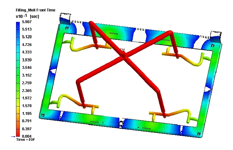
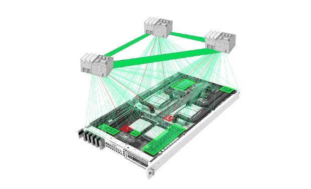
Example image from Moldex3D
To address these issues, you will want to have your tooling team review the part and tool designs at the DFM stage and make sure your suppliers document their process parameters. Photos of the process and components going through FAI measurements and documentation of their pass/fail criteria can help identify missing features and poor quality parts before they ship to the CM. Also, be sure to get the yield and inspection reports to refer back to in case of a discrepancy.
Early in a program, you may not have any choice but to build with these in-development parts. But, when you waive them for use, be aware of potential downstream consequences that may be caused by the part quality such as poor fit, cosmetic issues, or poor reliability performance.
Even when components arrive in the factory on time, they go through several steps before they can be assembled on the line. Parts are typically warehoused in your CM’s inventory. A sampling of these parts are taken to IQC for measurement, and in the process they might be moved between floors of the building multiple times to await the build. Failures found at IQC can lead to lot rejection and extra time spent unraveling whether the part is actually failing and who is to blame. Some of Instrumental’s customers have bypassed this time sink altogether by integrating test stations into their upstream suppliers letting the engineers have a single reference database showing them a clear picture of all parts as they move through the supply chain.
EXAMPLE:
Kindle Voyage Cosmetic Mid-Frame
- 10 different process steps:
- Factory 1
- Die-cast
- Rough Trim
- Fine Trim
- CNC 1
- CNC 2
- Passivation
- Factory 2
- Insert Mold with Glass-Filled Nylon
- Overmold with TPU
- Laser etching
- Adhesive Subassembly
3, FATP Process Failure Analysis
Once all your materials are on the line, issues often arise during the assembly process. We recommend having several extra sets of components that your process engineers and designers can use to physically follow the SOP and test stations to validate the assembly processes and set pass/fail limits.
Standard operating procedures may be a cause for concern if the steps are poorly defined or unclear. While the documents are often written in both English and the native language, operators may not be able to read and rely on training from line leaders. Ensure you have consistent line leaders during a build and if possible from build to build and be sure they understand what they are supposed to be doing. It should also be clear the possible issues might come up if they do something incorrectly. Using images with graphical overlays can help convey the process intent more clearly and highlighting example failures can help train them to catch issues before it becomes a pattern. Failed components or assemblies are also useful illustrations to compare against. In some cases, operators who don’t fully understand the SOP, they may prefer to do an operation in an easier or more careless fashion that creates inconsistencies in your prototypes so having someone on the ground to watch the process is important. During COVID-19, you may want to make use of photos and videos to document the process for later.
If you want to check 100% of your parts for a certain assembly, you can make use of Go/No Go gauges to determine if a given part will be acceptable. This will be faster than 100% measurement because these gauges should easily allow good parts to continue in the process while immediately identifying and rejecting bad parts. However, simple gauges are not the most useful for collecting and storing data about each component in a traceable manner. Tools like Instrumental’s Optimization Platform and image data can help bridge this gap by taking photos of every serialized component and device for future reference.
In functional test stations you may have inconsistent performance because the board hasn’t been designed well, or because the test station itself has issues connecting to the device under test. In addition, firmware to bring up your board may not yet be finalized. A bad driver might cause a test to fail and lead your team down a hardware chase when a software fix might be the answer. Make sure that the relevant software and hardware teams review the issues together during the FA process. If a jig or test station was calibrated and validated before the build, you should be much more confident in identifying poor performing devices. If a lot of devices are failing, you may want to expand your limits
If your team can’t be on site, make sure the CM team on the ground records each step of the assembly process and test with video and photos. Sometimes steps taken outside of the assembly stations can cause issues so ask to follow an entire unit from beginning to end. For even better oversight of a remote build, Instrumental’s test stations can be incorporated at key points to not only take images of each station, but also can proactively highlight discrepancies across different assemblies after only a few sets of data.
4. Reliability Failure Analysis

Example photo from Memeburn.
Once a prototype is complete, you will likely uncover failures during reliability testing. These tests are designed to push your product to its limits and replicate actual use by your future customers.
If you are building something for the first time, it can be useful to create simulations of certain mechanical tests such as drop testing. Once you complete your reliability test, compare how your devices actually performed with their simulated performance.
Sometimes, you might feel lucky if you did not uncover any failures, but in this case, you should consider the possibility of a false negative result. Also, be wary of making products that merely pass a specific controlled test because the real world can be more complicated. Most designers will hardly ever question passing results, but fight like hell to come up with plausible outside explanations for why they might have failed including blaming the test, poor materials, or assemblies. To combat this bias, test to failure with your early prototypes. All products will fail, you just want to know what the conditions are that will make it fail.
With reliability testing, it is crucial to get as much detail about the products that fail as possible including any critical assembly images, functional test results, and the waterfall sequence of reliability tests the device in question went through. Instrumental’s manufacturing optimization platform gives you easy access to serialized product image data and any test station information that you want to integrate. You can use this platform to do a reverse lookup on failed reliability devices to quickly aggregate the vast amount of data you have and get a jump start on your failure analysis process.
5. Unexplained Failures
The last category of failures are the real head scratchers. These are the ones where your detection methods have failed and there is no obvious place to start. You can’t always predict how or why they occur or they may only show up at the end of reliability testing, which may delay your program. Failure analysis with incomplete product data can further delays exponentially when the failure itself is unexpected.
These are the most confounding because it means that the product made it through all of the defined checkpoints along the way and still managed to escape. Perhaps one of the many steps in your development is not well controlled or understood, or it could be that something that you weren’t paying attention to suddenly becomes your top issue.
Some of the most challenging issues are a combination of many minor factors that only under certain circumstances manifest. Issues come up all time as consumers use the products in new ways in different environments around the world.
With these types of problems, it is best to return to first principles and document everything that you know about the issue and review all the steps along the way to look for possible sources of variation.
Next Steps
Reflecting on your past programs, see if you can find a pattern of where the most challenging issues occurred. If you have noticed any common sources of error, adjust your product development processes to better catch issues next time before they snowball into major issues. From a log of the issues at each build you can create generalized checklists for the next program to use. By recording who found and solved the issue you can build up a great set of resources for future designers to turn to if they run into similar problems.
If you have been able to establish great processes for preventing issues but still have some tricky unexplained failures to solve, look out for the next installments where we will review some great methods and tools to use in FA and will dive into some key questions you can use to interrogate any issue.
Do you have a story to share about a challenging failure your team resolved? Where did you find it and how did you fix it? We’d love to make a case study out of it! Contact communications@instrumental.com to get connected.
Author
Related Topics